In Search of the Ultimate
Model T Cylinder Head by Hugh Coltharp and Daniel Wright |
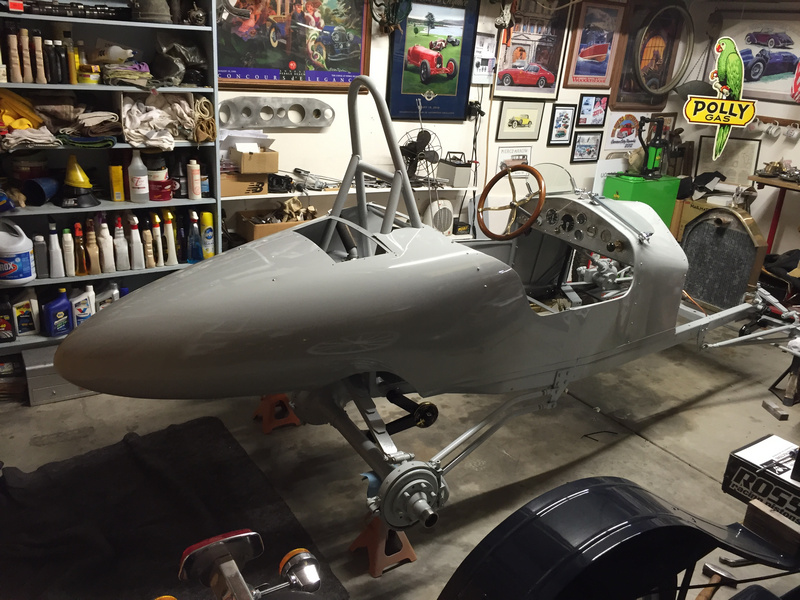
The first production Model T was produced on August 12, 1908 and
left the factory on September 27, 1908. Turns out that people are still building and competing with these antiques. Among my many Bonneville Racing friends, I know of several building replicas of early Milestone cars powered by ‘T” and “A” power plants. Some of these people have had a lifelong "Need for Speed".
So it wasn’t all that much of a surprise when I was asked whether it might be possible to build a Specialty Cylinder head for a High Performance T engine build. The Key to this Head design was the Flathead combustion chamber design
developed by Ken Kloth of Kloth Speedworks. Ken spent years laboring
over his Superflow FlowBench, developing a superior combustion chamber
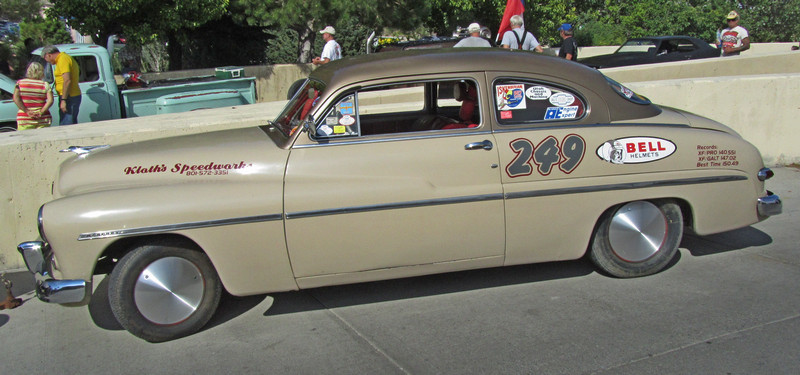
for the Ford V-8. Kens novel design was proven by setting a variety
of Flathead Competition Class records in LandSpeed Competition at
Bonneville. Bonneville Competition under the SCTA rules and classes
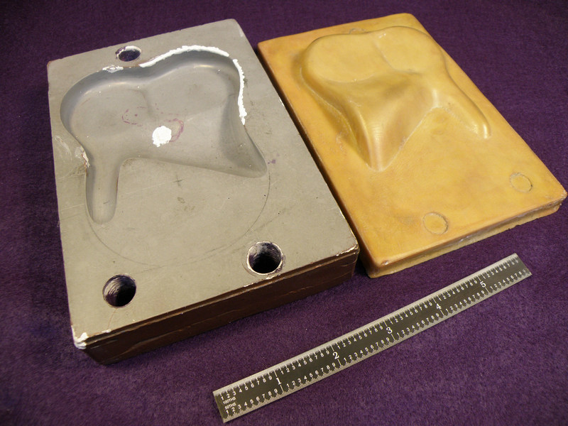
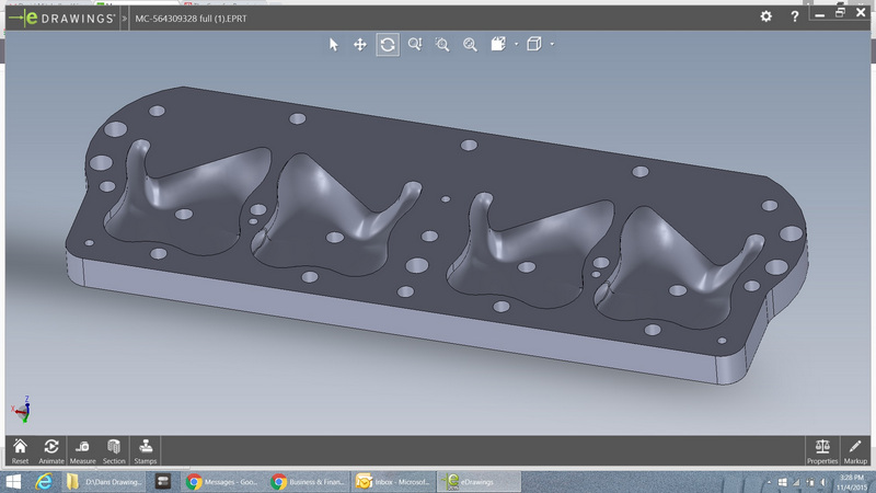
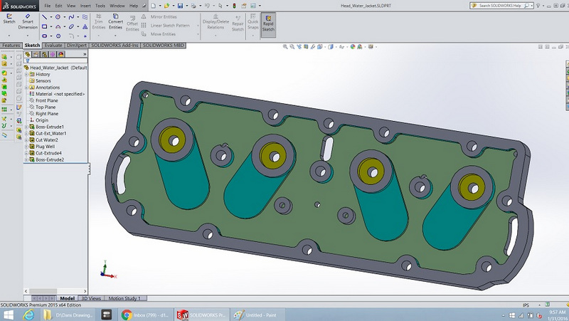
is perhaps the toughest testing laboratory in the world. Not only did he set Bonneville records, but he did it running a full size 1949 Mercury. That big ol’ 2 door Sedan with no modifications to improve aerodynamics is more linebacker than ballerina. But it was FAST. It was fast because it Breathed Better. And it Breathed Better, (a lot better) because of the Flowbench developed Combustion Chamber design. So the discussion began on whether that Better Breathing Chamber design could be apploed to Flathead engines other than the V-8. That talk somehow ended up in with a requet to redesign and fabircate a cylinderhead with that combustion chamber for a Model-T engine. So what we now have is a plan to use the latest technology tools in out work to create a cylinderhead for a one hundred year old engine. The tools we used included SolidWorks CAD design Software, Laser cutters, 3-d Printers and CNC macnining. We started by creating a Cad Design. Working from castings created from the the original cylinder head we recreated the Combustion Chamber shape in the correct size and spacing to fit the Model T dimensions.
Silicone and Epoxy Casts from the Original flowbench designed cylinder head. Measuring and recreating these smooth flowing organic shapes was a difficult Solidworks exercise. Solidworks is a great tool for mechanical shapes. It is much more difficult to draw complex organic shapes. We finally got our design drawn and ready to verify.
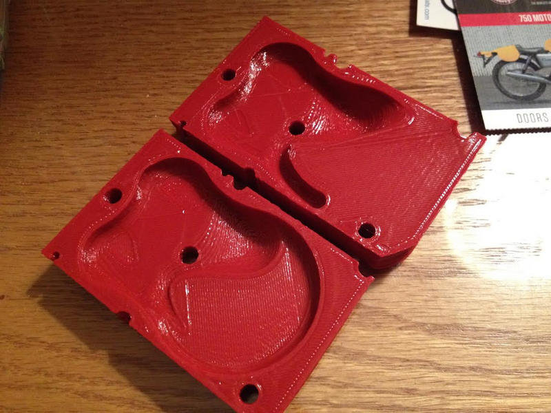
Once we had a 3-D Computeer model, we 3-D printed a couple of samples to help us to tell that we had approximated the correct shape.
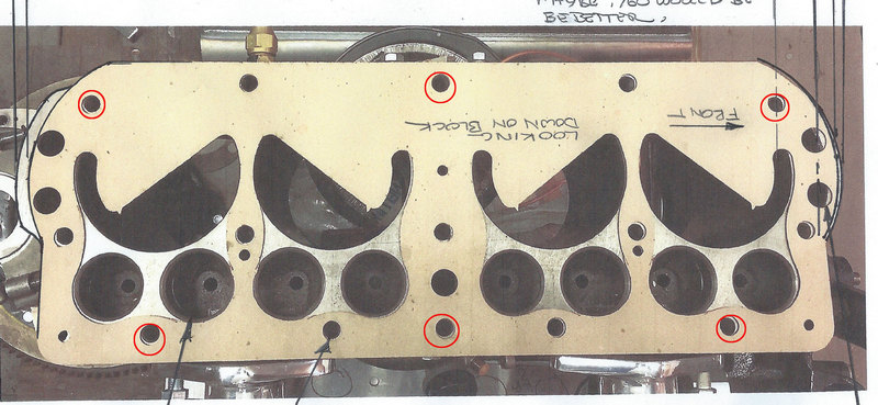
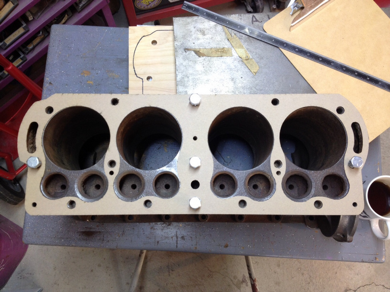
The printed parts were helpful in pointing out where we needed to refine our design and make corrections. We also had concerns about how our design fit the engine block. Were the cylinder bores properly located? How about water passages and headbolt holes? In order to verify all of these critical details, we tuened to a CNC Laser cutter. Using simple cardboard we cut a test piece to see how things lined up.
As you can see in the photo, not everything lined up perfectly. The holes circled in red all needed adjustment some of the water passsages needed revision, and we needed to add a bit of meat to each end. This marked up photo shows a bit of how this "Design by Committee" process worked. We would move a step forward, circulate photos and ideas via email among the small group and then make the agreed upon changes. Then we would repeat the process until we had a design that everybody was satisfied with.
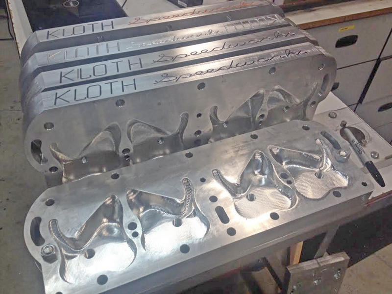
Once we were happy with our spacing and dimensions we had to figure
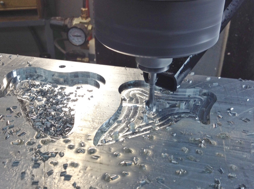
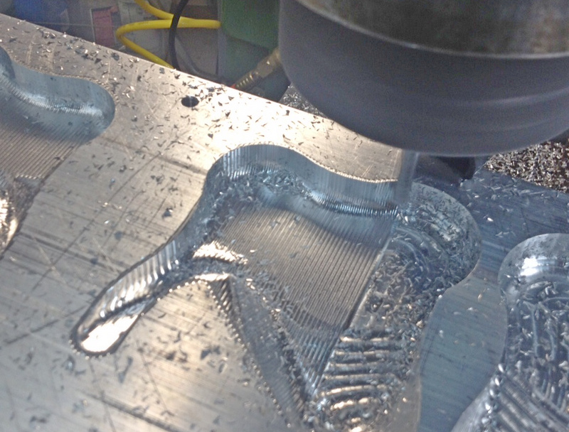
out how to machine the real piece. We knew we wanted to work in aluminum,
but we wanted to test our ability to create CNC Macning code that
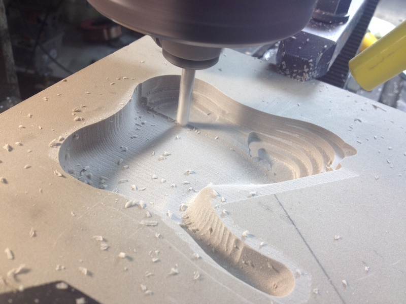
would cut the complex combustion chamber shape. Rather than do our
learning in aluminum we chose to experiment with some Tooling Foam.
Tooling Foam is a rigid polyurethane that cuts easily and holds excellent
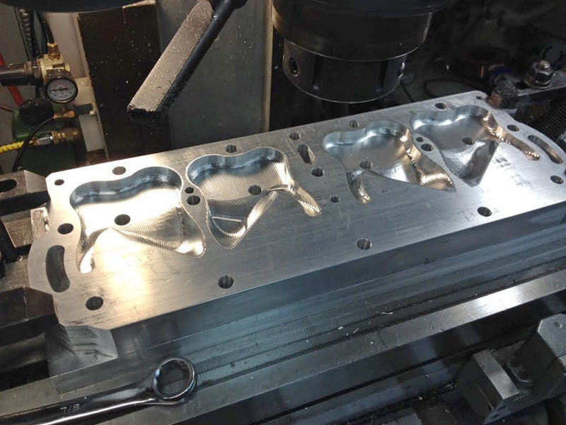
detail. As always seems to be the case, our first look at the produce in 3-D showed us mistakes and flaws that were not redily apparent on the computer screen. We changed several small details and then we setup to cut the real thing in aluminum.
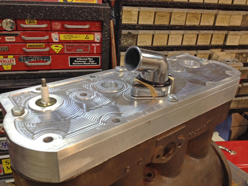
There is one item left to be done. We needed to provide for cooling water to flow thru the cylinder head. To do that we relieved a large portion of the aluminum from the top side of the head and added a "lid" to contain the water.
|